Address
304 North Cardinal St.
Dorchester Center, MA 02124
Work Hours
Monday to Friday: 7AM - 7PM
Weekend: 10AM - 5PM

Address
304 North Cardinal St.
Dorchester Center, MA 02124
Work Hours
Monday to Friday: 7AM - 7PM
Weekend: 10AM - 5PM

Explore aluminum die castings for UAVs, including weight, stiffness, thermal paths, vibration and production planning.
Aluminum die casting can support UAV motor mounts, camera brackets, avionics housings and structural interfaces when the design is reviewed for weight, vibration and production volume. Aluminum is not automatically the best material for every drone part. Instead, the decision depends on stiffness, flight loads, thermal requirements and the expected number of units.
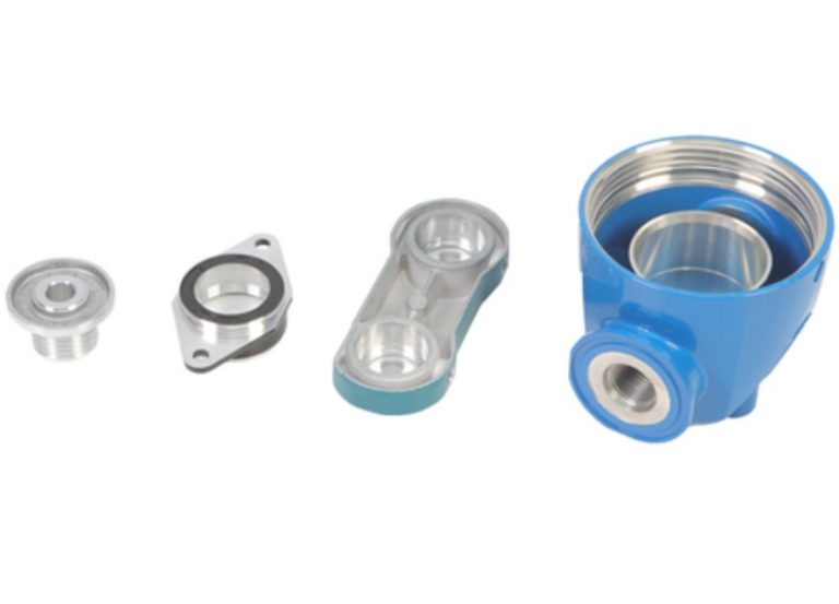
High-pressure die casting can form complex shapes with ribs, bosses, mounting pads and shallow cable paths. Because these features are integrated into one part, the assembly may need fewer components and less build time.
Thin-wall carbon structures, machined billet parts and die castings can coexist. The best design uses each process where its weight and manufacturing economics fit the application.
Reducing mass can improve flight time, but a flight-critical part also needs stiffness and reliable attachment. A thin casting that flexes under motor thrust can disturb alignment or change the load path. Therefore, review ribs and local bosses as part of the complete structural system.
When possible, machine or cast stable bearing pads around fasteners. Because clamping pressure can distort a thin wall, the mounting design should spread the load. After the load path is clear, the team can evaluate where mass reduction is practical.
Common high-pressure die-casting alloys provide useful strength and casting performance. However, the exact grade should follow the application and engineering specification. Before approving a material, confirm mechanical requirements, environmental exposure, finishing and any heat-treatment assumptions.
If the design is still changing, machining may be a better route for the first prototype. For production, high-pressure die casting can become economical when the geometry and demand justify the tooling investment.
UAV components often reduce material until the wall becomes difficult to fill or handle. During DFM review, compare the thinnest section with the longest metal-flow path. In addition, confirm that every part surface can leave the die without scuffing.
Use draft in the direction of die opening. When a side feature creates an undercut, compare a slide with a secondary machining operation. Although both options can work, each adds different cost and maintenance requirements.
Ribs can add stiffness without a heavy solid section. At the same time, thin and tall ribs may cool too quickly. Therefore, review the rib pattern with the casting process rather than treating each rib as an isolated feature.
Aluminum conducts heat, which can help transfer energy from a power device into a housing wall. However, the real thermal path also includes interfaces, gaps and fasteners. Consequently, the housing should be tested as a system rather than judged by material conductivity alone.
For an enclosure that needs electromagnetic compatibility, the joints, gasket and grounding path are important design features. Openings and cable entries can affect shielding. Test the assembled design because material choice alone does not guarantee the required performance.
Motor imbalance, propeller forces and landing impacts create vibration. Sharp corners and abrupt section changes can concentrate stress. Because fatigue depends on the real load path, add radii and locate fasteners through stable bosses where geometry allows.
Review the casting with the mounted equipment in place. The mass and stiffness of a camera, battery or payload can change the load path. As a result, an isolated CAD review may miss an important interaction.
Anodizing, powder coating and other finishes can affect color, electrical contact and dimensional fit. Before production, define which surfaces need conductivity or masking. After coating, confirm whether any threads or bearing seats require additional machining.
If the UAV housing must resist water or dust, define the gasket surface and leak criterion. Moreover, a visual surface check does not prove that a sealed assembly will pass an ingress test. Verify the complete enclosure with a suitable functional test.
First-article inspection should cover both the casting and downstream operations. Therefore, agree on datum features, critical dimensions, fixtures and inspection methods before tooling. During production, use in-process checks to protect sealing surfaces, fastener locations and structural interfaces.
For pressure-tight or water-resistant components, define a leak test that matches the assembly requirement. For cosmetic parts, state the viewing distance and acceptable surface area. In this way, quality decisions become measurable instead of subjective.
| Requirement | Information for the supplier |
|---|---|
| Flight application | Load path, vibration source and duty cycle |
| Geometry | Latest model, drawing, mating parts and mounting interface |
| Alloy | Specification or required mechanical performance |
| Volume | Prototype, pilot and expected annual quantity |
| Environment | Moisture, temperature, impact and corrosion exposure |
| Quality | Critical dimensions, finish and leak requirement |
A successful UAV casting combines lightweight design with enough stiffness, draft and support for the die. Begin with the broader aluminum die casting guide. Then review our tooling and die casting capabilities.
For a prototype program, compare die casting with precision CNC machining. Once the design and volume support tooling, send the CAD model, flight-load assumptions, target alloy and quantity through our drawing RFQ.
The North American Die Casting Association provides additional industry resources for material and design reviews. Use those references with the actual aircraft requirements, because a generic material property does not replace validation of the mounted assembly.
