Address
304 North Cardinal St.
Dorchester Center, MA 02124
Work Hours
Monday to Friday: 7AM - 7PM
Weekend: 10AM - 5PM

Address
304 North Cardinal St.
Dorchester Center, MA 02124
Work Hours
Monday to Friday: 7AM - 7PM
Weekend: 10AM - 5PM

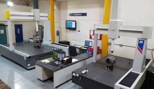
Specify aluminum die casting tolerances without over-constraining the process. Review fixed and moving die sides, parting lines, datums and inspection.
Aluminum die casting tolerances should separate what the part must achieve from what the process can repeat economically. A drawing with very tight tolerances on every dimension is not automatically better. It may simply force extra machining, increase inspection time and create disagreements at first article.

Identify the dimensions that locate mating parts, seal a joint, carry a bearing or control a safety-related function. These are the dimensions that deserve special attention. Dimensions that only describe a non-critical web, a clearance pocket or an internal transition can usually use a broader general tolerance.
If the drawing does not show which dimensions matter, every dimension looks equally important to a quotation reviewer. The result is either an inflated price or a process that attempts precision where the product does not need it.
Features formed on one die half are affected by shrinkage and die wear along the die-opening direction. Features that span the parting line add another source of variation. The same nominal dimension may therefore need a different tolerance depending on its direction and location.
This is why copying a single tolerance table onto every aluminum die casting drawing can mislead the supplier. State the applicable standard and identify exceptions, rather than assuming that every linear dimension is controlled in the same way.
RCM Industries lists commonly referenced NADCA tolerance information that can help frame the initial drawing discussion.
Aluminum die casting tolerances should follow the direction of the feature. A dimension measured across the die opening will not necessarily behave like a dimension within one die half.
| Feature type | Typical drawing approach | Verification |
|---|---|---|
| General as-cast geometry | Broad general tolerance | Sampling or fixture check |
| Critical fit or sealing feature | Explicit tolerance and datum | CMM or dedicated gauge |
| Machined locating surface | Machining stock plus final tolerance | First article and in-process check |
| Cross-parting-line feature | Review capability with die caster | Functional gauge or CMM |
The values belong in the final drawing after the process and inspection method are agreed. A supplier should not discover a tolerance requirement only when the first sample is measured.
A datum tells the inspector and machinist where measurements begin. Cast surfaces can move as the part cools. If the primary datum is a small, angled or flexible area, every later measurement inherits that variation.
Use stable cast pads or machined surfaces as locating features when possible. Show enough of the datum structure to establish six degrees of freedom. For a machined part, explain whether the datum is established before or after the casting operation. This distinction affects fixture design and the order of inspection.
An as-cast tolerance controls the geometry immediately after ejection and trimming. A machined tolerance controls a surface produced by a later operation. The latter can be much tighter, but it is not free. It requires stock, fixture access, cycle time and inspection.
If a feature has a tight position relative to a machined bore, define the functional relationship. Avoid dimensioning from an unstable cast edge when a machined datum would reflect how the part is assembled. Review the machining requirements and fixture access before adding stock to every surface.
GD&T can make a drawing clearer when it reflects the function of the part. It can also create an impossible inspection requirement when the tolerance zone and datum sequence conflict with the casting process. Use position, profile and flatness only where the assembly needs them.
For a curved visible surface, a profile tolerance may be the right control. For a mounting pad that must sit flat, flatness and a datum may be more useful. Avoid applying both a global profile control and tight local dimensions unless the relationship is intentional.
State whether dimensions apply before or after coating, plating or anodizing. Include the temperature and measurement method only when they change the acceptance decision. For thin walls, consider how the part will be supported during CMM inspection; a measurement taken on an unsupported casting can differ from one taken in a fixture.
Send at least one marked-up drawing that highlights the critical dimensions. If only the CAD model is available, explain which features are functional and which are approximate. The engineering team can then propose a tolerance scheme and identify any feature that requires a slide, an insert or a secondary machining operation.
Document the agreed aluminum die casting tolerances in the first-article plan. The inspection method should match the drawing, not a generic visual check.
Use the same revision of the model and drawing during quotation. A supplier may price one revision while the buyer later expects another, leading to tooling changes and schedule delays.
Before you finalize the drawing, use our aluminum die casting design guide to check draft, wall thickness and parting-line placement. For a tolerance review, upload the drawing and current model with the areas that control fit and function.
